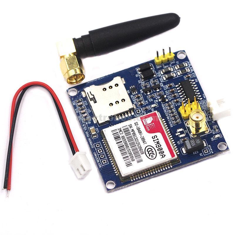
SIM900A V4.0 GSM GPRS Kit PAKISTAN
2,450.00 ₨
SIM900A GSM GPRS module The serial port circuit: support for 3.3V single chip microcomputer. TTL serial port support 3.3 and 5V single chip microcomputer.
The SIM card circuit to increase the SMF05C ESD chip.
Antenna circuit: guarantee short and straight, so as to ensure the signal strength.
PCB display screen printing mark: each interface, convenient development two times, the SIM900/A hardware is completely follow the design when the design manual.
Two power supply interface: VCC5, 5V DC above 1A. Computer 5V power supply can be early computer USB. DC long data circuit over larger recommended 5V1A. VCC4, 3.5-4.5V power supply, ibid., suitable for lithium battery.
Control pin all leads.
A TTL level, compatible with 3.3V and 5V.
The two antenna interface, the default SMA straight head, connector for IPXmini antenna.
One way of speech interface, the way Mike interface.
The control interface of each pin description:
GND – GND
SIMR SIM900A RXD, TTL level, can not be directly connected to the 232 level
SIMT SIM900A TXD, TTL level, can not be directly connected to the 232 level
RST – SIM900A reset, active low
VCC_MCU when the SIM900A module and 5V TTL level communication, this pin is connected to DC 5V; when the level of communication of SIM900A and 3.3V TTL, this pin is connected to DC 3.3V
VCC5—-DC 5V input
VCC4——DC3.5–4.5 input
Onboard Resources:
Serial port circuit (with protection)
Antenna interface circuit (SMA bend female port)
SIM card circuit (flip SIM slot)
4*3.5 fixture hole 4pcs
SIM900A serial port output terminal
Specifications:
Size: 50mm x 48mm
Net weight: 28g
Weight: 38g
Package Included:
1 x SIM900A GSM GPRS module
1x Power Cable
1x Antenna
SMS Send Receive Example code
Connect GSM RX pin to Arduino Digital pin 9
GSM TX pin to Arduino Digital pin 10
GND should be common with Arduino GND and provide atleast 1A 5V supply to GSM module.
Cop and paste the code below in arduino IDE.
//ERFINDER CODE
#include <SoftwareSerial.h>
SoftwareSerial mySerial(9, 10); // RX, TX
void setup()
{ mySerial.begin(115200); // Setting the baud rate of GSM Module
Serial.begin(115200); // Settingthe baud rate of Serial Monitor (Arduino)
delay(100);
}
void loop()
{ if(Serial.available()>0)
switch(Serial.read())
{ case ‘s’:
SendMessage();
break;
case ‘r’:
RecieveMessage();
break; }
if(mySerial.available()>0)
Serial.write(mySerial.read());
}
void SendMessage()
{
mySerial.println(“AT+CMGF=1”); //Sets the GSM Module in Text Mode
delay(1000); // Delay of 1000 milli seconds or 1 second
mySerial.println(“AT+CMGS=\”+92300XXXXXXX\”\r”); //Replace x with mobile number
delay(1000);
mySerial.println(“Iam SMS from GSM Module”);// The SMS text you want to send
delay(100);
mySerial.println((char)26);// ASCII code of CTRL+Z
delay(1000);
}
void RecieveMessage()
{
mySerial.println(“AT+CNMI=2,2,0,0,0”); // AT Command torecieve a live SMS
delay(1000);
}
Be the first to review “SIM900A V4.0 GSM GPRS Kit PAKISTAN” Cancel reply
Related products
Arduino interface Module
Arduino interface Module


Reviews
There are no reviews yet.